Per request.A quite a big revision of this circuit was made a couple of years ago making it a worthwhile addition to the blog. The general topology remains almost the same but lots of component values have been updated.
Trimpots is added for easier biasing.
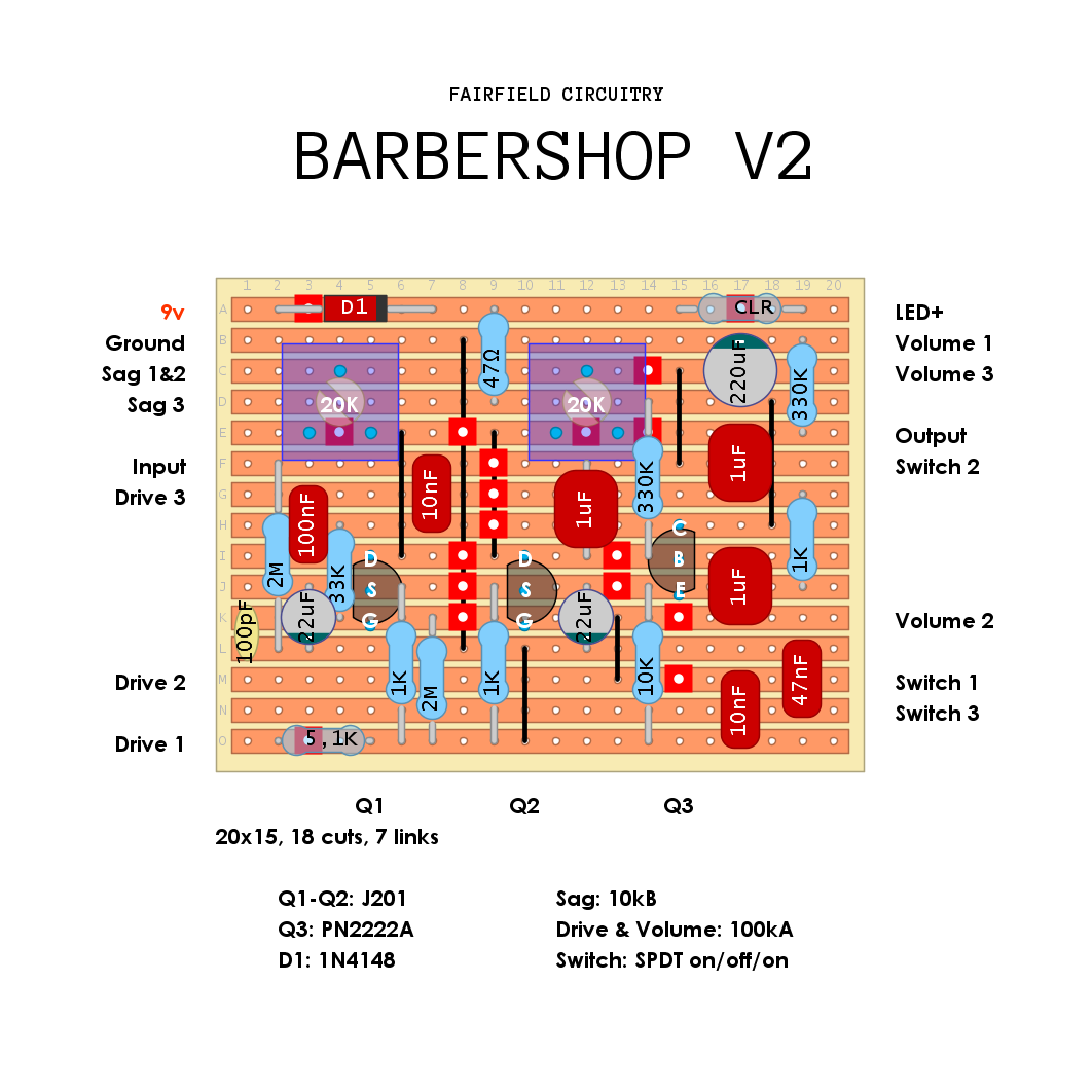
Schematic is avaiable HERE.
That’s quite surprising. I had this pedal from 2021 and it had 4 trimmers and smd J201’s. I’m guessing this must be an earlier V2.
ReplyDeleteI tried to find info on what the other two trims would even do. One is for maximum drive according to Fairfield. But internally It's simply labeled "Bias". The fourth is labelled "Sag" so it must effect how the Sag control sweeps. Interesting.
DeleteThis comment has been removed by the author.
DeleteThe bias trim seems to be linked to the PN2222A, but mine had three smd transistors, not two.
DeleteFound this in an old email from Fairfield:
DeleteThe gain trim pot is typically set around 5 o’clock (looking at the circuit board with the foot switch at the bottom).
The position of the sag trim pot varies quite a lot, so to set this, set drive and sag to minimum, and the volume to maximum. The sag trim pot will now set the ‘maximum’ amount of sag (i.e. the sound when the sag knob is at minimum).
Oh interesting. Well in the end I'm sure they all are shooting for the same basic effect. I love the way the V1 sounds. I don't know exactly what it is. Mainly it's for the fact that you can place it anywhere. It works well as a boost and if you boost into it you just get more Barbershop. I like fuzz into it and recently I've gotten more into Klons pushing it. It's pretty versatile. It's simple and a bit dull on its own but it seems to do just about whatever you want it to.
DeleteCouldn't agree more. It's a really cool circuit!
DeleteIt's VERY different. I was never happy with the barbershop I made....
ReplyDeleteThis comment has been removed by the author.
ReplyDeleteThis is verified. It sounds good. I may tinker with a few values to get some of the control that Ben mentioned. I typically starve the bias of the FETs a hair in this circuit. The PN2222A that I used worked a lot better than the 2N2222A that I tested with. Thanks for this one Anders.
ReplyDeleteThanks Tom.
DeleteTagged.
built and everything seems to be working except that all i'm getting is a MASSIVE clean boost. been over the circuit a few times and I can't find any errors. JFETs bias perfectly.
ReplyDeletefor anyone who's build or played one, how dirty should this thing get with the gain all the way up?
Yeah, it doesn't get super dirty. Some would call it a boost. I like to under bias the FETs a little. The way this circuit shines is in how it drives other pedals or amplifiers. And if you hit the circuit with a boost or drive it will ooze tweedy overdrive. Use the controls to fine tune what you're getting from it. I don't even use the tone switch, but it's there if you need it.
DeleteSo voltages for the JFETs should be around -3V or so, not the typical -5V. Maximum dirt when the Sag knob is fully clockwise. Ben actually mentioned this in another post and I confirmed it elsewhere. I thought I had been under-biasing. Nope
DeleteThat was it--had my fets biased to 5v. Set them to 3v and now everything sounds more or less like the demos I've seen. Thanks, Tom!!
DeleteCan you tell me where the knobs should be set when biasing the jfets? sag, volume? thanks
ReplyDeleteThis comment has been removed by the author.
DeleteThis comment has been removed by the author.
DeleteIt should draw a maximum of 6.66V from Q1 and Q2 leaving the last approx 3V for Q3. So with the Sag control fully CW you want to draw roughly 3.33 volts for Q1 and Q2. Once the Sag gets below noon it'll starve the circuit and make it cut out. Sort of like the Smallsound/Bigsound Mini. Also, no static pop in this version. Some guys use a 2n3904 in Q3 which sounds cool too.
DeleteOk. So sag at max and 3.3v for jfets. I'll give it a go. Thanks Tom
DeleteI think I'm wrong...the bias resistor on Q1 is 8.2k and Q2 is 11k so the way I have this biased is off. I was looking at a V1 today and realized the error. I think the proper way to do it is to get 6 volts on each of the resistors at max voltage. So it will hang around 3 volts closer to the middle of the sweep. Sorry, I knew that and second guessed myself. I feel stupid. Sorry if I caused confusion.
DeleteThanks for this layout, sounds amazing !
ReplyDeleteAccording to schematic R10 on 1M are missing in layout.
ReplyDeleteI've seen 1N5817 instead of 1N4148 used in other layouts/schematics - I assume it's just protection but is there is advantage to using 4148 instead of 5817 in this case?
ReplyDeleteProbably not. I think Anders was just respecting the choice of the original designer. It's just power protection. Why Fairfield chose that? Maybe someone smarter knows.
DeleteBest guess as a dilettante: most protection diodes guard against reverse polarity but not overvoltage. 1N5817s have a forward current maximum of 1 amp, which could cook the Barbershop (which has an incredibly low current draw of 5 milliamps) if there was a power surge. 1N4148s have a maximum forward current of 300 milliamps, so any surge larger than that would blow the diode before hitting the rest of the circuit. The 1N4148 has double the voltage drop off a 1N5817, but in a circuit with individually-biased FETs, that doesn't particularly matter.
DeleteThanks :) I had built two of them, I love the Barbershop and the way you can go from clean to OD just by playing on the attack. Works fine with a bass too, and is very cool behind a fuzz (tone bender ). If you like the Barbershop you may like the "about 900 fuzz", much more fuzzy but with the same color of the sound.
ReplyDelete