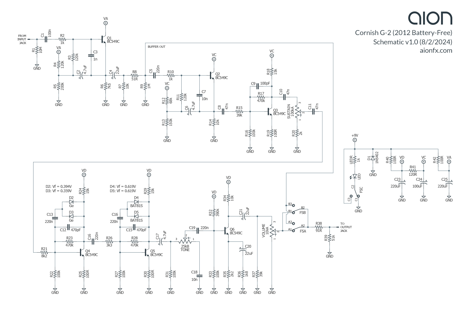
Schematic and more info is avaiable HERE.

Another contribution by Jordan. Thanks mate!
.png)
Another contribution by Jordan Fontaine!
Schematic is avaible HERE.
This on is verified and good to go.

Phew, loys of work lately so not much time for the blog and building lataely. A few people have sent me some new traces and new layouts. These will be uploaded today. First out is Little Acid Fuzz by Frost Giant Electronics.
Another Frost Giant PCB traced by Sergio. Based on the op amp version of the Little Big Muff from the late 70s. The internal Tone trimmer can easily be moved to the outside for a 2-knobber.

Based on Skreddy Screwdriver but Mr Bones modified into quite something else...
Schematic is avaiable HERE.

How about a MOSFET/Germanium Harmonic Percolator with some extra controls? And silicon/infrared diode clipping? Chuck D. Bones Spunk-O-Matic has it all...
Schematic is avaiable HERE.

Schematic is avaiable HERE.


Once again, Ian Sheridan sent me another one of those DBA business card circuits to trace.


Schematic is avaiable HERE.
I added a "Boost" control at the end of the circuit since this thung is supposed to be quite loud.

An old forgotten madbean project based on the pre amp section of solid state Squier 51 amplifier. I really find these SS amp designs interesting and they usually ditorts in an interesting way. The op amp types aren't specified in the schematic but I bet TL072 will work fine. You can also try op amps with bad specs like LM1458 or LM358, things might sound more fuzzy and dirty with these.

.gif)
...and Ian also wanted to contribute with a layout....TCHULA!
Verified and good to go.

Jordan sent me a layout and of course it qualifies as an entry on the blog. Still unverfifed, though.

Here is a contribution from Chris Stelloh that seem to be really useful.
Chris says:
This is an updated version of the Demedash Incandenza micro-controller
free clickless relay true bypass switch. It takes up a bit more room
than a simple 3pdt, but because of the friction-free operation of the
SPST button, it will last WAY longer than that same traditional,
mechanical 3pdt switch. I realize that most folks will not want to build
an extra board where just a footswitch will do... but for those of us
that DO, here's my drawing of a super-slick, silent, clickless relay
that doesn't require any coding or microcontrollers. There are a few
earlier versions of this circuit floating around the web, but this one
has a very important update from Steve Demedash himself. The power
filtering and 100 ohm resistor between the 555 and the relay is super
important. I found that the power spike when engaging the flip flop was
enough to mess with other circuitry that was close to the switch. For
example: I had a dual circuit build with independent on/off switches and
triggering one would sometimes trigger the other one unintentionally.
Anyway - here's a boring utility layout that has ended up being the
thing I build the most, since I put these in just about any circuit that
will permit it. This layout also allows you to omit the polarity
protection diode for the main board and the status LED as well since
those are both contained here on this switch daughterboard. The 5v DPDT
relays you can use for this are not limited to just these three -
however, these three are the smallest and most inexpensive I've found so
far. Also - I don't like to use standing axial components or 3-row
resistors but in the case of this board, I wanted to keep it as small as
possible. Be sure and notice the anode of D3 connected to ground!