Schematic avaiable at FSB.
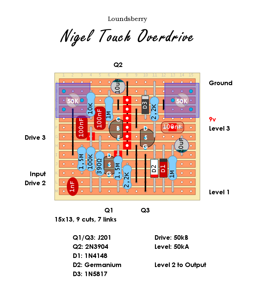
Subbed the 6,8k Drain resistors for a couple of 50k trimpots for easier bias setup.
Schematic avaiable at FSB.
Subbed the 6,8k Drain resistors for a couple of 50k trimpots for easier bias setup.
Analog Man's take on the old and quite rare Sam Ash Fuzzz Boxxx/Astrotone Fuzz. Bigger input and output caps and a resistor swap at the tone control should make this a different animal compared to the vintage pedals which suffered from lack of bottom end and a useful tone control. Various transistors has been used, often in "black dot" casing. Try NPN silicon with hfe 150-400.

Per request. A few things changed compared to the schematic; Bass ctrl outer lugs swapped, the two parallel 220uf power filter caps changed to a single 470uF (but you will get away with a 220uf or 100uf...), series protection diode added and bypass mute switching is omitted. SCHEMATIC.

This was a request. here is a change to try out your low gain and low leakage soviet transistors in a Tonebender Mk. II. There is a trimpot for each transistor and an onboard voltage converter for daisy chaining. The schematic specifies MP40 for all transistors but I bet other should work and sound good as well like MP41, MP42, MP20, MP21, GT308, GT402 etc, etc, etc. Just mind the pinout for the GT series transistors. Vero - Point2Point Layouts has a spreadsheet for for most NOS russian transitors HERE.
You can also build a Marshall Supa Fuzz by upping the 5uF (....or4,7uF) capacitors to 10uF or a Vox Tonebender Mk. II by upping both 10nF caps to 15nF.

Recently traced by Aion Fx, here is the 8 transistor version of CB30. It is supposed to be a very good sounding Vox-esque overdive. With 8 transistors it was quite difficult to keep the size down but it will fit into a 125b with no problem.
Schematic, tracing journal and more info at Aion Fx.

Evilarsen traced a unit from 2015 last week and not surptisngly, it is a Rat derivate. However, the "One" and "Two" controls should give you more tonal options than a stock Rat.

Schematic and BOM avaiable at OSH Park.
Looks like a very interesting Matamp/Orange amp emulator running mostly at almost 36v with an active speaker simulator(?) and a "Mode" switch for two tonestacks. Each being at different locations in the circuit.

Another take by Dunwich Amplification on the mighty HM2 circuit. Just released as a DIY project at OSH Park it has some tweaks all along the circuit compared to the stock Boss schematic. It also has a built in active clean blend circuit and switches for both hard and soft clipping diodes.
Schematic and BOM can be downloaded at OSH Park.

...and a layout with "Dope-Ass Lower-Tuned" values for the gyrator eq section requested (?) by MTK.
These values were calculated by Ryan from Heard Sound Circuits and makes things sound....more evil.
(Low: 62,48 Hz, Mid: 716,67 Hz, High: 1065,5 Hz)

Here we have a "little" monster layout for a DIY project that Dunwich Amplification just released at OSH Park. It is supposed to a emulate a part Al Cisneros of Sleep bass rig. It is basically three circuits in parallell, a DOD 250 Pre Amp, a Boss DS1 and a clean J FET boost with a James tonestack.
Schematic and BOM can be downloaded HERE.

This one shares almost the same footprint as the earlier "Big Box" version but component values have been changed all across the circuit. No major changes except for the "bass boost" cap/resistor at the Cut switch and a few extra caps and resistors.
Schematic is avaiable at FSB.

The layout is based on a quite diffucult-to-read schematic found at Mod Wiggler forum.
It may contain some errors and there are few question marks next to some of the pots and one of the caps, so some "trial and error" might be necessary to get this thing working as it should. Also, the "Filter" switch looks like a feedback switch for the LM386 IC and it appears to be a panel mounted push button switch but I guess a SPST toggle switch can be used as well.

Deadend Fx just traced this rare beast and released a PCB for it. Go and get it!
If not, here is a couple vero layouts for the fuzz section. I will upload the Boost section once I can wrap my head around some of the switch connections....
There are two layouts, one stock the with internal 8-pole DIP switch and one with all switches converted into 8 external SPST toggle switches.
Schematic HERE.
Unverified stock version


A bit modified compared to the schematic to keep it 1590B friendly. The relay bypass switching is omitted and so is the bicolour LED indicator. The circuit itself is quite "normal" compared to other Spaceman circuits and there is only one odd part; TLE2426 which is a precision virtual ground regulator. Layout is based on schematic avaiable at Deadend Fx.


