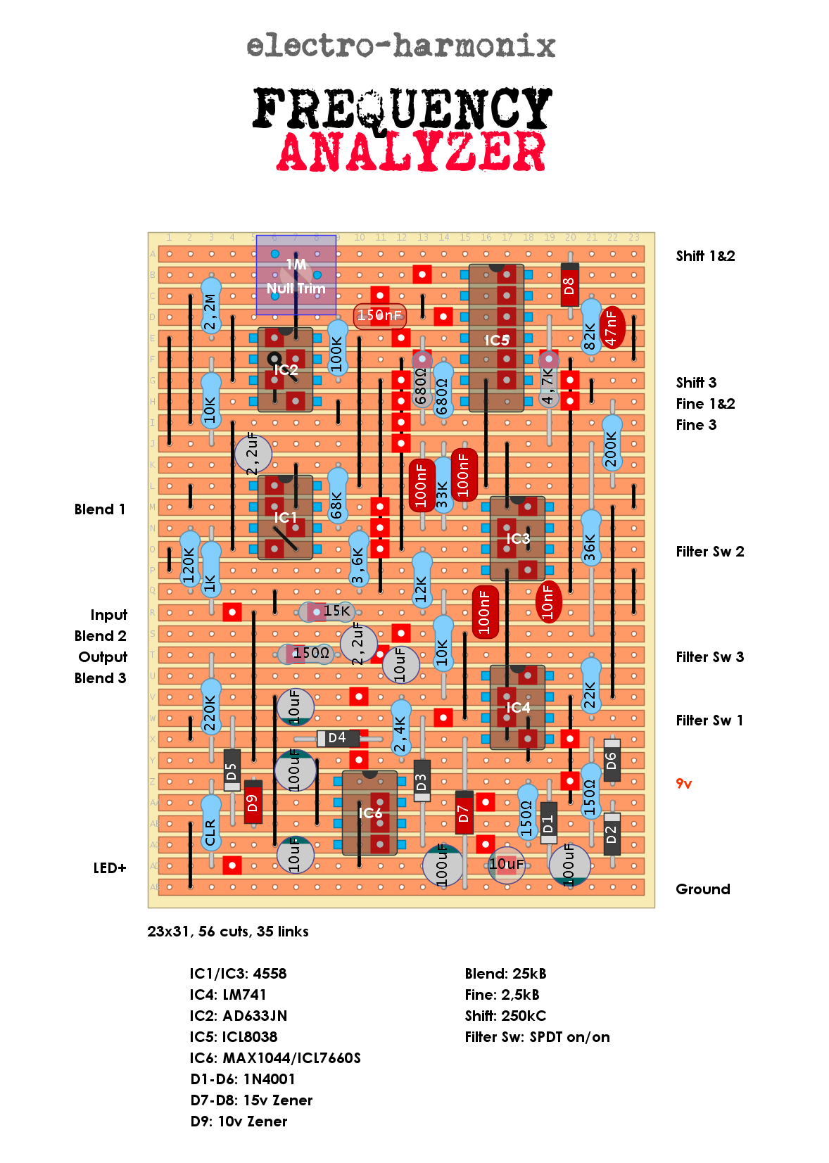
The modern version of EHX Frequency Analyzer. The ICL8083 IC is obsolete but there is still some vendors that have it in stock. Came out taller than expected since I wanted the bipolar voltage doubler circuit on the same board as the main circuit. But it will fit sideways in a BB enclosure...
Schematic is avaiable HERE.
hi Fuzzhead, is it possible to build a looper redal like ditto looper?
ReplyDeleteI'm afraid not. It involves digital and memory ICs and possibly programming. Way to complicated to do on vero.:-/
DeleteThe closest you could easily build to something like that would be a lofi sampler using an ISD1820 chip typically used in old answering machines. Lonershy on YouTube has a great tutorial on building one using the prepopulated pcb's which are readily available, I picked up a pack of 5 of them on Amazon that I'm putting into a single enclosure. It can be used as a 20 second looper in repeat mode but this is definitely not a perfect solution, there is a small gap between the end and beginning of the loop but it can produce some interesting results nonetheless. The lofi nature makes it unique and changing the pitch of your loop can be lots of fun. If you wanted to build a looper without that gap or audio deterioration you'd probably be looking at building the looper with an arduino chip instead, I'm certain that others have done this already as well and it's possible someone has provided the code to do so but I haven't spent much time with Arduino or Raspberry Pi yet myself. Definitely something I'm interested in expanding my knowledge of.
Deletethanks for that, had a stupid idea that an answer phone ic would do
ReplyDeleteNononono, not a stupid idea at all! It is an interesting idea! I guess searching the forums for a DIY looper might result in something doable for stripboard?
DeleteI’m only counting 56 cuts. Can someone check me on that?
ReplyDeleteI count 57 cuts.
DeleteAdded an image for only the links and cuts for an easier overview of the mess....:-)
Thanks! This will help a lot. I think this is the most cuts and links I've ever attempted. Crossing my fingers and hoping to have this verified before week's end.
DeleteThis comment has been removed by the author.
ReplyDeleteWait...I'm still only counting 56. 56 red squares. Confused. Counted five times. Am I having a stroke? Are you counting the double link spot by mistake?
ReplyDeleteNo, you're having a stroke...it turns out that I am blind and can't count...:-/
DeleteYes, I finally counted 56 cuts as well.
Oh good! Proceeding with confidence on this build then.
DeleteWell, shoot, I didn’t make it. I’m not getting enough voltage into the circuit. Pin 8 of IC 1 is reading 1.64v, so I started tracing the power section. I have 9.42v going in. Drops to 5.77 at the 150r junction, then 2.86v at the anode of D1, same at anode of D2. Now, I did use a TC1044SCPA, is that a problem? I usually don’t have a problem using that in place of a MAX 1044, but right now in this circuit the readings are all screwy. Nothing coming out of there higher than 2.86v.
ReplyDeleteHmmm, wierd. Ok, I doubt the the charge pump are the problem. What's the reading on pin 5 of of it?
DeleteYou can try to feed 9v straight into pin 1/8 to if the voltage goes up.
Built this last week, had fake AD633 and had supply voltages dropped to +/-4V! Proper AD633A arrived today and it still didn't work.
ReplyDeleteFound out there's no output on the ICL8038 - checking with the schematic, it seems the right side (Pins 10, 11, 12) are connected wrong in the layout.
After fixing that, it works, but the filter has a lot of hiss - seems Filter Switch 2 and 3 are swapped (as compared to the schematic).
Anyway, after the above fixes, it's working now!