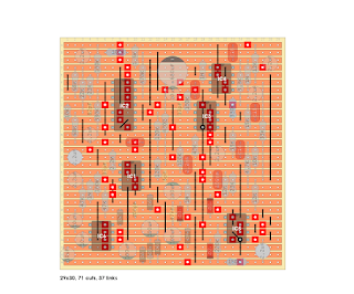
Ok, let's release the beast. Two layouts. One stock for iether Bass or Lead cap values.
And another one with a Beta/Lead switch. Since I'm not a big fan of offboard wiring I decidied to simplify things a bit. Lead cap values is always in circuit and with a 4PDT switch you can switch in four caps in parallel so it matches up with Bass values. Some values differs in few hundred pico farad or a few nano farad but the overall difference is minimal. And in theory you could use a SPST switch....
It also has an onboard charge pump for 15v/-15 operation.
This going to be the last layout I will post in a while since I'm going back to work tomorrow but this and a few other layouts should keep some of you occupied....;-)
*Edit*
MTK once again outdid himself! Here is a short demo of Lead/Bass switch version.
Stock layout.


This was a 5 hour project. I don't even wanna know how long this layout took. lol Thanks for finding time for this one, man. I appreciate it.
ReplyDeleteBoard - https://i.imgur.com/gJyK7Cz.jpg
Demo - https://www.youtube.com/watch?v=dReZ1UGBj2k
You are a madman!
DeleteThanks for taking YOUR time to building it and fix the charge pump issue.
Tagged!
Happy to help. I was talking with Alex about how to get more gain out of it and he recommended taking out R1 and R5 and using jumpers. That did the trick. I only jumpered R1 and it was enough extra gain for me. Just took this circuit to 11 in my book.
DeleteHi MTK. By R1 you mean the 47k resistor in input? And R5?
DeleteI'd build it stock and see if you need more distortion.
DeleteThe 120k at S-13 and the 1M at S-18 make up the gain stage after the drive pot. Or maybe you can bump up the gain stages on the 4069. You don't want to accidentally change the tone in some drastic way.
I bet since this is a preamp, it would be a good candidate for using a boost pedal.
Now the tone control, what's going on there?
What is the little black hole under IC5?
ReplyDeleteThat is two links in a shared hole a.k.a. "doublelink".
DeleteThank you!
DeleteDone: https://www.youtube.com/watch?v=FK6Xl9_B0W0
ReplyDeleteHowdy, folks! Can anyone out there share IC voltages on this bad boy? I have it built and am getting a heavily gated, and just generally crappy-sounding effected signal, as well as constant, really loud 7K-ish and 14K-ish tones. Any help would be appreciated!
ReplyDeletehey there, i just built it and have the same issue (somewhat), did you end up getting it going?
DeleteHi! I'm trying to replicate the Lead/Bass circuit in Proteus, but I'm having trouble reading the layout without the schematics, do any of you guys have the schematics to share?
ReplyDeleteCheck this out.
Deletehttp://effectslayouts.com/wp-content/uploads/2020/01/SunnBeam-build-doc.pdf
It looks like several are available on freestompboxes.org
ReplyDeleteHi!
ReplyDeleteWhat do you think, can I use MAX1044 or ICL7660 instead of LT1054?
I made it using TC4069 instead of CD4069 and the sound was perfect, but there is a loud noise like oscillation all the time. Is there any solution?
ReplyDeleteHi, I believe there is a fault on the Vero!! The 10k resistor should move point N26 to P26.... following the schematic it should connect to the 2u2 like the 56n/22n and 15k do, however, here it's getting connected after the 56n/22 and 15k. I'd imagine that does change how the bass pot is responding.
ReplyDeleteHello long time lurker builder. I’m having trouble getting my guitar signal through the circuit. I just get oscillation at the output. I did use a 470 uf cap wondering if that’s the issue. I’ve gone over all the connections and everything looks good. Any ideas what to try? Maybe bad op amps.
ReplyDeleteLike Chris has mentioned above, there is an error in the layout. I built this a few years ago and it never sounded right, very little bass (the bass control didn't do much other than cut) and very thin/harsh sounding compared to the actual amp (which I own and was able to compare it to). I've revisited it and following the schematic also found that the top leg of the 10k resistor (N26) needs to connect to the bottom leg of the 2.2uf cap as per the schematic. Once you move that leg down to P26 the bass control will work as it should (loads of bass!) and the whole thing will sound much closer to the amp.
ReplyDeleteI built this, and it sounds great. I can't believe it works... I have rarely built anything this big and complicated! But it only took 2 or 3 rounds of troubleshooting and it rips! I do think the above comment about moving the 10k resistor is correct. When I first got this working, it didn't seem to have a ton of low end, but making that change made a huge difference. I haven't tried to look at the schematic to verify it, but it is a significant improvement.
ReplyDeleteBuilt this with the switch for Bass/Lead operation. I made the above suggested change of moving N26 down to P26, and it works great! I had built the tagboardeffects Beta before, but I much prefer this layout. The integration of the charge pump just makes it so much easier. Thank you!
ReplyDelete