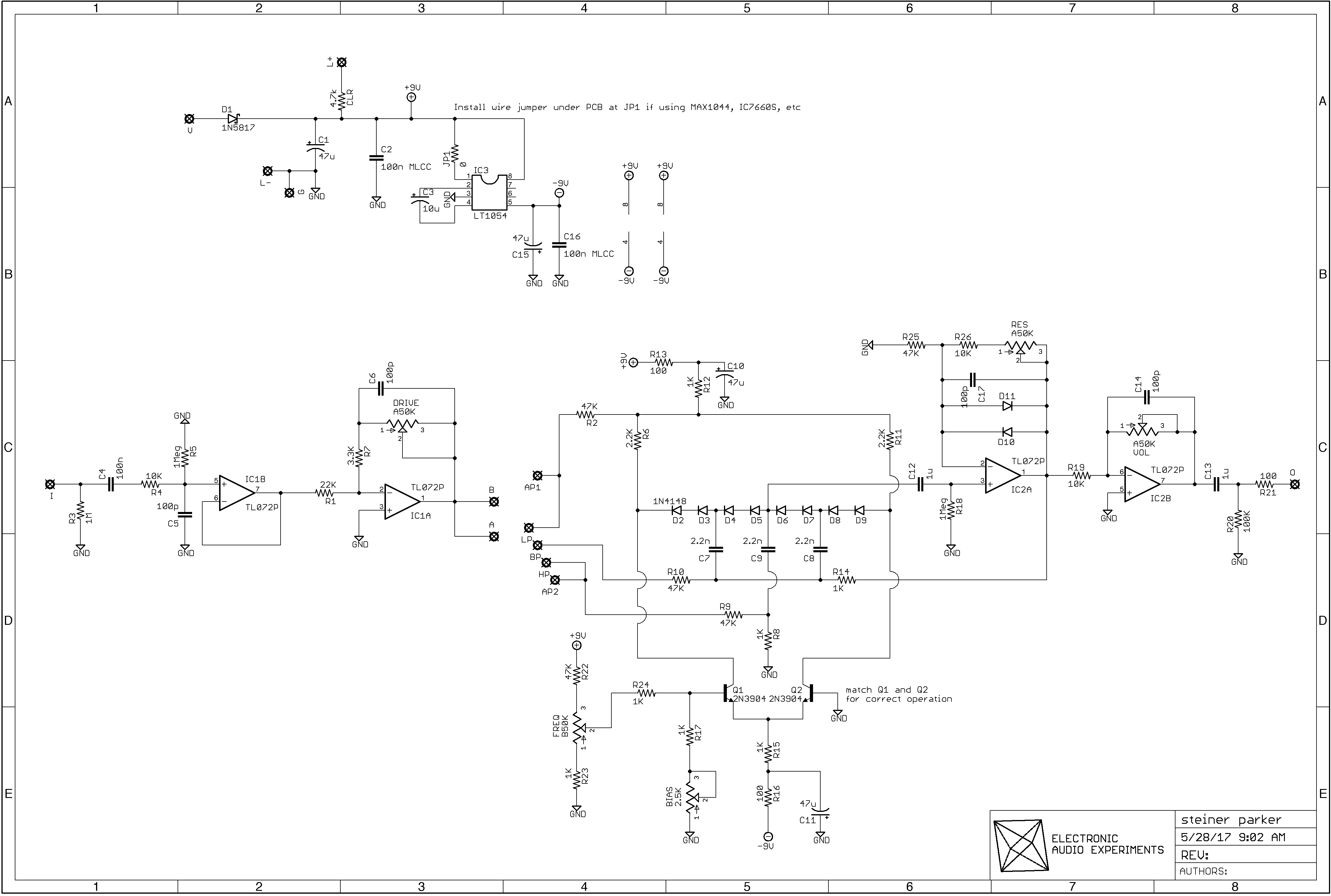
there is a Steiner Parker filter on a drum machine that I own - so I'm going to try and build this up to see if I can approximate a standalone version of that. I may end up playing with the resistors that limit the freq pot to get it closer to the original design - according to EAE - they added these to limit the freq range to be guitar specific. also, per their notes, if you want to use a MAX2004/7660 charge pump, you can just omit the cut between pads 1 & 8 on IC3.
I'm kind of fixated on this one for the moment - I built my first attempt up today... but hardly any sound at all. I'm looking over the schematic (which is a mind bender - I'm super impressed with how Anders laid it out here) and I think that both the drive pot and the bias trimmer may need to be tweaked a little to fit the schematic. I'll report back here if I get it licked.
okay - redrew this layout using most of the original in order to correct the bias trimmer wiring issue, as well as the connections to both the collectors on the transistors, and I'm still getting the same issues - when I turn the volume and driver all the way up I get a barely audible signal. The freq knob has no effect and the filter mode rotary selector doesn't really seem to be doing anything either. Think I am going to throw in the towel on this for now and maybe come back to it later.
redrew this yet again based on recommendations from EAE as well as to correct a couple of connection errors and I am still getting the same problems as I noted earlier in my comment from November 24th. I matched both the transistors and the three 2n2 capacitors and I am still barely getting a signal in two of the modes and getting no signal at all in the other two. Think I am going to throw in the towel on this one.
Hey Chris, I spot two errors: I think you were referring to Q1 needing to connect to cathode of D1, which is doable with a couple of changes. I also noticed that a cut is needed at S21. I know it’s been a bit, but please post any other errors you spotted. Thanks! Rick
Circling back to this one after a while away and I'm seeing a bunch of those errors. I think I may sit down with the schematic for this and the original and try to hammer out my own drawing to correct it. Sorry for the extremely late reply - I got frustrated with this one and had to put it away for a while but am ready to get it sorted now.
Well... I think I am truly ready to be done with attempting this one. I redrew the layout and corrected all of the connection errors, matched both the three 2n2 capacitors to each other, as well as the pair of transistors. And I'm STILL getting the same results as before. During my attempts to build this, I've actually emailed with John at EAE to get his advice, and I'm still stumped by this one. Two modes work but are super quiet, two modes don't work at all. I'm going to say I've made my last attempt at this one. Especially since I am quite fond of the nasty incongruent filtering and buzzy resonance of the Haible Wasp.
The thing that has vexed me the most is that, aside from a higher voltage power supply and a few part value differences, the versions of this that are in use by those in the modular universe is pretty dang similar to the EAE layout. I really had no luck trying to compare this one to other layouts trying g to figure out where the signal was getting bogged down. 🤷

there is a Steiner Parker filter on a drum machine that I own - so I'm going to try and build this up to see if I can approximate a standalone version of that. I may end up playing with the resistors that limit the freq pot to get it closer to the original design - according to EAE - they added these to limit the freq range to be guitar specific. also, per their notes, if you want to use a MAX2004/7660 charge pump, you can just omit the cut between pads 1 & 8 on IC3.
ReplyDeleteMAX1044 I mean
DeleteI'm kind of fixated on this one for the moment - I built my first attempt up today... but hardly any sound at all. I'm looking over the schematic (which is a mind bender - I'm super impressed with how Anders laid it out here) and I think that both the drive pot and the bias trimmer may need to be tweaked a little to fit the schematic. I'll report back here if I get it licked.
ReplyDeleteokay - redrew this layout using most of the original in order to correct the bias trimmer wiring issue, as well as the connections to both the collectors on the transistors, and I'm still getting the same issues - when I turn the volume and driver all the way up I get a barely audible signal. The freq knob has no effect and the filter mode rotary selector doesn't really seem to be doing anything either. Think I am going to throw in the towel on this for now and maybe come back to it later.
Deleteas I remember build the yusynth STEINER VCF before, Q1 & Q2 need to matched, and those 2n2 caps need to be matched also.
Deleteredrew this yet again based on recommendations from EAE as well as to correct a couple of connection errors and I am still getting the same problems as I noted earlier in my comment from November 24th. I matched both the transistors and the three 2n2 capacitors and I am still barely getting a signal in two of the modes and getting no signal at all in the other two. Think I am going to throw in the towel on this one.
ReplyDeleteI see the trimmer issue you mentioned. Also: IC1 pin 4 connected to -9V instead of ground.
DeleteHey Chris, I spot two errors: I think you were referring to Q1 needing to connect to cathode of D1, which is doable with a couple of changes. I also noticed that a cut is needed at S21. I know it’s been a bit, but please post any other errors you spotted. Thanks! Rick
ReplyDeleteCircling back to this one after a while away and I'm seeing a bunch of those errors. I think I may sit down with the schematic for this and the original and try to hammer out my own drawing to correct it. Sorry for the extremely late reply - I got frustrated with this one and had to put it away for a while but am ready to get it sorted now.
DeleteWell... I think I am truly ready to be done with attempting this one. I redrew the layout and corrected all of the connection errors, matched both the three 2n2 capacitors to each other, as well as the pair of transistors. And I'm STILL getting the same results as before. During my attempts to build this, I've actually emailed with John at EAE to get his advice, and I'm still stumped by this one. Two modes work but are super quiet, two modes don't work at all. I'm going to say I've made my last attempt at this one. Especially since I am quite fond of the nasty incongruent filtering and buzzy resonance of the Haible Wasp.
DeleteI put this on a breadboard and can only get HP to pass signal. Freq. pot does nothing. EAE knows their stuff. What gives with this thing?!?!
DeleteThe thing that has vexed me the most is that, aside from a higher voltage power supply and a few part value differences, the versions of this that are in use by those in the modular universe is pretty dang similar to the EAE layout. I really had no luck trying to compare this one to other layouts trying g to figure out where the signal was getting bogged down. 🤷
DeleteRight?! Im going back to the drawing board and trying this one:
Deletehttps://www.eddybergman.com/2020/04/synthesizer-build-part-26-steiner-vcf.html?m=1
We shall never speak of this schematic again.
Every public space needs this. sandwich vending machine
ReplyDelete