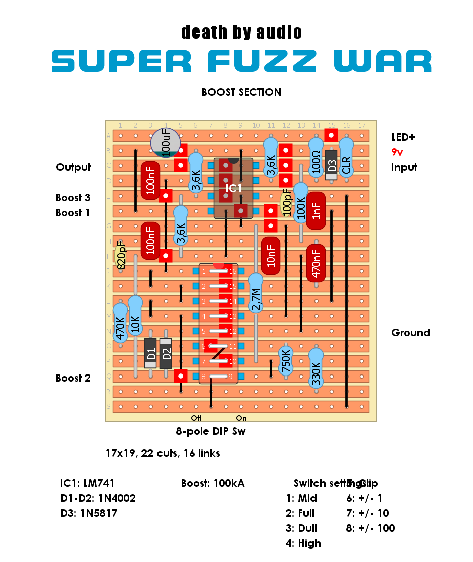
"Hey Ross. Just uploaded the booster section. https://dirtboxlayouts.blogspot.com/2021/06/death-by-audio-super-fuzz-war-boost.html The big question is pin 8 and 9 for the slider switch. According to the schematic they are joined together which makes no sense. But the the PCB images at DeadEnd Fx reveals that there is seprate traces for pin and 9... https://www.deadendfx.com/product/skirmish
We can continue the this topic in the "Boost section" post?"
Amazing, I'll get to this soon when I have a chance :)
Pin 8/9 needs a cut... Schematic does actually show a S2.8 label coming off the 100p (which also matches the PCB image) but then doesn't list it on the dip switch part. Error on documentation by looks
This layout doesn't work. Built it two separate times, both built to the letter, quadruple checked for mistakes and shorts, all components tested. It simply doesn't work.
"Hey Ross. Just uploaded the booster section.
ReplyDeletehttps://dirtboxlayouts.blogspot.com/2021/06/death-by-audio-super-fuzz-war-boost.html
The big question is pin 8 and 9 for the slider switch. According to the schematic they are joined together which makes no sense. But the the PCB images at DeadEnd Fx reveals that there is seprate traces for pin and 9...
https://www.deadendfx.com/product/skirmish
We can continue the this topic in the "Boost section" post?"
Amazing, I'll get to this soon when I have a chance :)
This comment has been removed by the author.
DeletePin 8/9 needs a cut... Schematic does actually show a S2.8 label coming off the 100p (which also matches the PCB image) but then doesn't list it on the dip switch part. Error on documentation by looks
DeleteI'm starting to build this and the fuzz section, done in a week hopefully :-). I can tell you at the moment the layouts actually 17x19 big.
ReplyDeleteYeah, it is 17x19.
DeleteThis comment has been removed by the author.
ReplyDeleteBuilt and all working. Just needs a cut added between dip switch 8 and 9 and you're good. +/- 1 and +/1 10 are real subtle but they're there.
ReplyDeleteI've got this as a full blown super fuzz war (using the super fuzz board layout on here too)
This layout doesn't work. Built it two separate times, both built to the letter, quadruple checked for mistakes and shorts, all components tested. It simply doesn't work.
ReplyDeleteOdd! The layout matches the schematic. Have you tracked the signal through your build with an audio probe?
Delete